
 |
|||||
 |
|||||
Next: Consistent Landmark Thin-Plate Spline Up: Methods Previous: index
Unidirectional Landmark Thin-Plate Spline Registration
The unidirectional landmark-based, thin-plate spline (UL-TPS) image
registration algorithm [1,2,23] registers a template image ![]() with a target image
with a target image ![]() by matching corresponding landmarks identified in both images.
Registration at non-landmark points is accomplished by interpolation such
that the overall transformation smoothly maps the template into the shape
of the target image.
by matching corresponding landmarks identified in both images.
Registration at non-landmark points is accomplished by interpolation such
that the overall transformation smoothly maps the template into the shape
of the target image.
The unidirectional landmark image registration problem can be thought
of as a Dirichlet problem [25] and can be stated mathematically
as finding the displacement field ![]() that minimizes the cost function
that minimizes the cost function
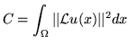 |
(1) |
subject to the constraints that
subject to the constraints that
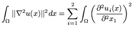
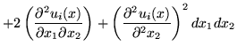
It is well known [1,2,23] that the thin-plate spline displacement
field ![]() that minimizes the bending energy defined by Eq. 2
has the form
that minimizes the bending energy defined by Eq. 2
has the form
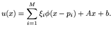
where
The thin-plate spline interpolant
![]() is derived assuming infinite boundary conditions,
i.e.,
is derived assuming infinite boundary conditions,
i.e., ![]() is assumed to be the whole plane
is assumed to be the whole plane ![]() . The thin-plate spline transformation is truncated at the image
boundary when it is applied to an image. This presents a mismatch in boundary
conditions at the image edges when comparing forward and reverse transformations
between two images. It also implies that a thin-plate spline transformation
is not a one-to-one and onto mapping between two image spaces. To overcome
this problem and to match the periodic boundary conditions assumed by
the intensity-based consistent image registration algorithm [32,34], we use the following procedure
to approximate periodic boundary conditions for the thin-plate spline
algorithm. In the future we plan to replace the following periodic approximation
method with an exact solution for the periodic landmark matching. This
will be important for extending the algorithm from 2D to 3D since the
computation time and storage requirements increase by a factor of 27 for
the 3D case.
. The thin-plate spline transformation is truncated at the image
boundary when it is applied to an image. This presents a mismatch in boundary
conditions at the image edges when comparing forward and reverse transformations
between two images. It also implies that a thin-plate spline transformation
is not a one-to-one and onto mapping between two image spaces. To overcome
this problem and to match the periodic boundary conditions assumed by
the intensity-based consistent image registration algorithm [32,34], we use the following procedure
to approximate periodic boundary conditions for the thin-plate spline
algorithm. In the future we plan to replace the following periodic approximation
method with an exact solution for the periodic landmark matching. This
will be important for extending the algorithm from 2D to 3D since the
computation time and storage requirements increase by a factor of 27 for
the 3D case.
It is assumed for all of the algorithms presented in this paper that the images being matched have the same field of view and that they contain the same structures. We further assume that the objects in the images are centered within the image and are padded with the background intensity.
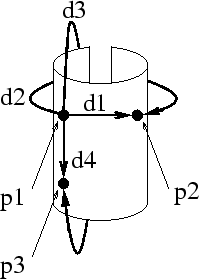
Figure 2 illustrates
the concept of periodic boundary conditions for the landmark thin-plate
spline registration problem. Cyclic boundary conditions implies a toroidal
coordinate system such that the left-right and top-bottom boundaries of
the domain ![]() are mapped together. Modifying the boundary conditions in this
manner causes an infinite number of interactions between landmarks for
a given finite set of landmark points. Panel
are mapped together. Modifying the boundary conditions in this
manner causes an infinite number of interactions between landmarks for
a given finite set of landmark points. Panel ![]() shows two such interactions between landmark points
shows two such interactions between landmark points ![]() and
and ![]() ; one within the domain
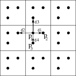
; one within the domain ![]() and another between adjacent image domains. We approximate the
solution of Laplace's Equation with periodic boundary conditions by solving
the TPS registration problem with replicated landmark locations in the
eight adjacent domains as shown in panel
and another between adjacent image domains. We approximate the
solution of Laplace's Equation with periodic boundary conditions by solving
the TPS registration problem with replicated landmark locations in the
eight adjacent domains as shown in panel ![]() of Fig. 2.
This provides a good approximation to periodic boundary conditions since
the the kernel function,
of Fig. 2.
This provides a good approximation to periodic boundary conditions since
the the kernel function,
![]() , causes interactions between landmarks to decrease
rapidly as the distance between landmarks increases.
, causes interactions between landmarks to decrease
rapidly as the distance between landmarks increases.
|
The inverse consistency error of the forward and reverse transformations generated by the UL-TPS can be made smaller by averaging the forward transformation with the inverse of the reverse transformation. This averaging will be referred to as the averaged unidirectional landmark-based thin-plate spline (AUL-TPS) algorithm and is used to initialize the consistent landmark TPS algorithm described in the next section. Note that this procedure does not significantly effect the error at the landmarks since the displacement at the landmark locations in the forward, reverse, inverse-forward, and inverse-reverse transformations are nearly zero as computed by the UL-TPS algorithm.
Next: Consistent Landmark Thin-Plate Spline Up: Methods Previous: index Xiujuan Geng 2002-07-04
Copyright © 2002 • The University of Iowa. All rights reserved.
Iowa City, Iowa 52242
Questions or Comments: gary-christensen@uiowa.edu