1. Data Acquisition Setup
- Model 5512 is ballasted to its dynamic sinkage and trim for Fr = 0.28 and
mounted on the tank centerline in the fixed condition.
- The PMM scotch yoke is adjusted for a 327.2 mm sway amplitude and a maximum
heading angle of 10.2°.
- PMM potentiometers are incorporated in the sway carriage and yaw linkage to
track the model maneuvers.
- Potentiometer cabling is run to onboard amplifiers.
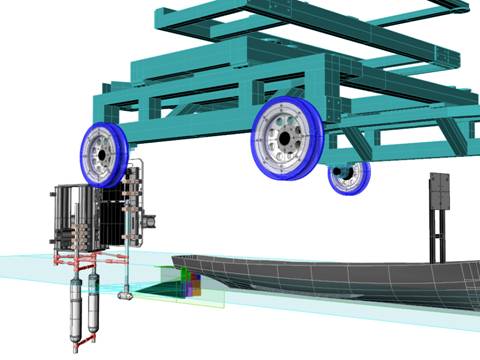
- The SPIV system is assembled on an automated two-axis (y, z)
traverse which slides on the 4 m strongback underneath the PMM carriage in the
x-coordinate.
- The laser and lightsheet optics are arranged to deliver a vertical lightsheet in
the (y, z) crossplane.
- Standoff distance between the lightsheet generator and the measurement area
center is 550 mm.
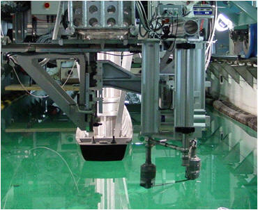
- The cameras are arranged with equal standoff distances between the enclosures
and the measurement area (880 mm), 33° of separation between cameras, and a 22°
angle between camera #1 and the tank axis to provide clearance with the model
and avoid an extremely shallow angle between camera #2 and the cross plane.
- A minimum separation angle of 30° between cameras is maintained to ensure good
measurement quality.
- Power, video, and trigger cables are routed through the strongback to the PIV
computer onboard the drive carriage.
- The laser power supplies ride aboard the PMM carriage.
- A single umbilical for coolant and electronics cables links the power supplies
and the laser head.
- Laser trigger lines also run through the strongback to the drive carriage PIV
computer.
- The SPIV computer is equipped with frame grabbers, a programmable timing unit, a
TTL/IO board, and an 8-channel AD board capable of synchronously acquiring
analog voltages and PIV recordings.
- An IIHR-designed and -built PIV synchronizer is used to provide
equally-spaced
trigger pulses to the SPIV computer in order to acquire PIV recordings at
presettable, repeatable phase angles in the pure yaw maneuver.
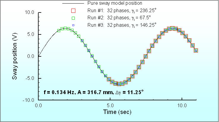
- This is achieved as the synchronizer monitors the analog output from the PMM
sway potentiometer.
- When a predetermined voltage corresponding to 45° on the rising side of the sway
curve is reached, the synchronizer emits a burst of 32 TTL’s, each having a 200
msec pulse width and a time between triggers of 233 ms.
- Since the pure yaw motion frequency is f = 0.134 Hz, this enables a
SPIV
recording every 11.25° equally spaced through one PMM period.
- The process is then repeated on subsequent PMM cycles.
Pure sway test:
Pure yaw test:
2. Data Acquisition Procedures
- First, the PMM is activated and ten seconds elapse to allow enough time for the
motion to reach a steady rate.
- A digital oscilloscope monitors the sway carriage analog voltage output and the
synchronizer triggers.
- When they are synched-up, the carriage is started and accelerates through 10 m
to a constant speed.
- Data acquisition commences after traveling another 10 m which allows the
unsteady free surface and flowfield to develop and reach a state where they are
not in transition.
- Data acquisition occurs at 4.288 Hz for 19sec enabling 80-90 SPIV recordings or
about 2.5 recordings per each of the 32 phases in the PMM cycle.
- At least 100 carriage runs are performed for a given measurement area position
to obtain enough recordings at each phase to achieve convergence of the data.
- Convergence is monitored as the data is acquired and data acquisition is
typically stopped when the residual in the velocities drops by two orders of
magnitude.
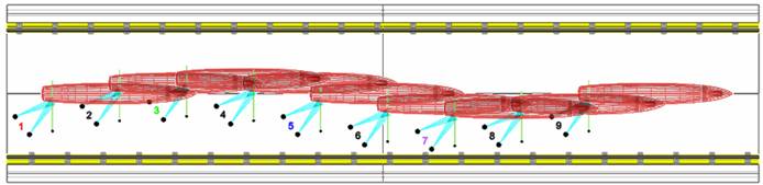
- Data acquisition is completed at several overlapping zones at each x-station
in order to piece together a complete picture of the region of interest.
- Four or five zones are used at each x-station to cover the region of
interest.