55:132/22C:160, Spring 2009
High-Performance Computer Architecture
Homework 4 (First Verilog Project)
Objective
You are to modify a Verilog model of a direct mapped cache to increase the line
size from one-word to two-words, as discussed below, and then investigate the
effect that different line sizes and overall cache size have on cache
performance.
Students may work individually or in groups to complete the assignment:
· Students working individually need only implement the change in line size from one word to two words.
· Students working in groups of two should implement the line size change and also modify the cache to be two-way set associative.
· Students desiring to work in groups of size larger than two should contact the instructor to negotiate an expanded scope for the project.
Specification
Verilog source code for a simple, direct mapped cache can be found here . Note: This code has been tested in the ModelSim environment and is known to run.
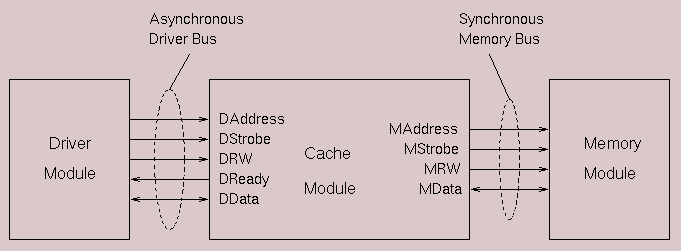
The following figure shows the two level memory hierarchy:

The cache size is 1024 lines and the line size is one word (32 bits). The cache write policy is write-through. The cache size is parameterized so that you can easily change it. However, you must keep the width of both the memory bus and driver bus at 32 bits.
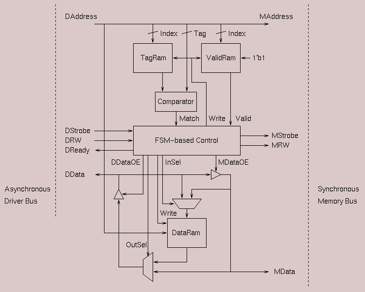
The following as a block diagram of the cache:

In the directory with the Verilog source code you will find two sample memory access trace files. The smaller file, tex.trc contains 100 memory references and is suitable for debugging purposes. The larger file, large.tex.trace contains 200,000 accesses, enough to generate meaningful data on cache hit rates, etc. Once you have your cache model working properly, you will need to run it using this large trace file. Note that the trace file to be used is specified in the header file trace.h.
Running
Cache Simulations
- The trace file is specified in the file trace.h.
To change the trace being run you need to edit this file.
- There are two levels of debugging information that can
be generated during a trace. To use these edit the file dbgflags.h
- You can change the cache size (# of lines) by editing
the cache.h header file.
- The top level module is in the file main.v
and is called Main. After compiling all of the modules,
you can start the simulation by typing vsim Main (or vsim
-c Main for the command line interface.)
- A run value of about 20000 timesteps will work for the
short trace, and 100,000,000 timesteps for the large trace. Be sure to
turn off the debugging information for the long trace. From the command
line, you can use the command run -all to run the
simulation for as many timesteps as needed for termination.
Experimental Study
Once you have your modified cache working properly, you should conduct multiple simulation runs to investigate the performance of various cache configurations. Specifically, evaluate the hit rate (read hit rate write hit rate, total hit rate) and total memory access time for each of the following configurations:
- One-word line size, 1024 words total cache size
- Two-word line size, 1024 words (512 lines) total size
- One-word line size, 4096 words total cache size
- Two word line size, 4096 words total cache size
- One word line size, 16384 words total cache size
- Two word line size, 16384 words total cache size.
Prepare a short report comparing the cache performance and total memory access time for each configuration. Note that as described above, you can edit the cache.h file to modify the size of the cache.
Submission
Before beginning your Verilog
coding, you must complete a suitably detailed schematic design diagram (a
modified version of the diagram shown above) indicating the modifications that
you wil make to the structure of the cache to permit increase of the line size
(and to provide 2-way set-associativity for those working as a team). This diagram must have sufficient detail to
allow evaluation of the efficacy of your
design approach. This diagram must be handed in a week before the final due
date of the assignment.
You are to submit all source code files for your cache that are either new or modified from the original (direct mapped, one-word line size) implementation, with a transcript file showing a run of your cache on the long trace (with debugging output disabled, please). You should also submit the text file containing your comparative evaluation of cache configurations as described above. Your Verilog code should be generously commented. The Verilog source files, transcript file, and text file should be compressed into a single tar file which should be submitted as an e-mail attachment to: hpca@engineering.uiowa.edu. If you are not familiar with how to create a tar file, consult this link.
Due
Date
Schematic design diagram: Thursday, March 5, in-class
Tar-file: Thursday March 12 by 11:59 pm.(e-mail submission)