55:132/22C:160
High
Performance Computer Architecture
Spring,
2011
Second
Verilog Project
Due
Dates: Thurs. April 7, Tues. April 12, Thurs. April 14, Tues. April 19
Objective:
This project is intended to enhance your understanding
of cache memory organization through experimentation with alternative cache
write policies and implementation of a set-associative cache. The project has
four parts with different due dates.
Part
1:
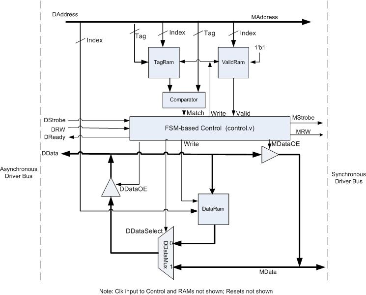
In this part of the assignment you will work with a
Verilog model of a direct mapped cache that employs a write-through,
write-allocate write policy. Specifically, you will investigate the impact of
cache size on performance. The Verilog code for the direct mapped cache can be
found here. Both individual files and a zipped
tar-ball are provided. The following diagram shows the overall structure of the
cache model.
The detailed structure of the cache itself is shown
in the following block diagram. Study this diagram and the associated Verilog
code and make sure that you understand it completely before proceeding with the
rest of the project. The class period on Tuesday, April 5 will be devoted to a
discussion of the cache model and the tasks required to complete the project.
The cache size is parameterized and can be changed
by redefining constants in the cache.h header file. Memory addresses are byte
addresses. However, all memory accesses are assumed to be one word (four bytes)
in size, and the cache size in cache.h is expressed in words. The Verilog code
for the cache includes two large memory access trace files, each containing
approximately one million memory accesses captured from runs of real programs.
The file large_cc.trc contains the memory access trace for an execution snippet
of a C compiler, and the file large-spice.trc contains the trace for an
execution snippet of a Spice circuit simulation. The trace file to be used for
a simulation run of the Verilog cache model is specified in the file trace.h.
Run the direct mapped cache model for each of the
trace files and for each of the following cache sizes 1K (1024) words, 2K
(2048) words, 4K (4096) words, 8K (8192) words, 16K (16,384) words, and 32K
(32,768) words.
Part
1 Submission:
Based upon these simulation runs, create the
following graphs:
1. Overall
cache miss rate versus cache size. Show curves for both traces on the same
graph.
2. Read
miss rate versus cache size. Show curves for both traces on the same graph.
3. Write
miss rate versus cache size. Show curves for both traces on the same graph.
4. Memory
read time versus cache size. Show curves for both traces on the same graph.
5. Memory
write time versus cache size. Show curves for both traces on the same graph.
Due
Date for Part 1: Thursday, April 7 by 11:59 p.m. Submit
via e-mail to hpca@engineering.uiowa.edu, hand-in to instructor, or leave in
ECE Office (4016 SC) by closing time.
Part
2:
For this portion of the
project you will modify the write policy of the direct mapped cache to:
write-back, non-allocate. A nearly completed Verilog model for the modified
cache is provided here. The structure of the
modified cache is shown in the following diagram:
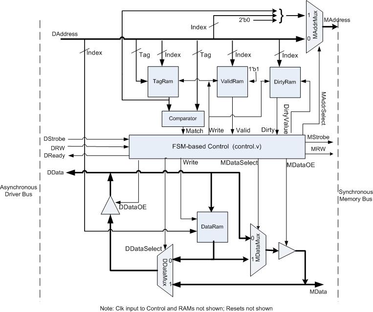
The specific changes made to the cache and its finite-state
controller will be discussed in class on Tuesday, April 5. The only portion of
the model that has not been completed for you is assignment of the controller
output signals in the task UpdateSignals in module control.v.
Your assignment for this portion of the project is
to complete the modified cache model by correctly specifying the control signal
assignments in control.v. You do not need to make any changes to cache.v or any
other modules.
To aid in debugging and verifying correct operation
of your modified cache, as short (12 entry) trace file, called short_test.trc
has been provided. You can use this trace file, in conjunction with the debug
and verbose options that can be enabled in the file dbgflags.h, to analyze the
behavior of your cache. Note: do NOT enable verbose or debug mode when using
one of the long trace files unless you are prepared to wait a very long time
for your simulation to complete. A necessary (but not sufficient) condition for
correct operation of your modified cache is that it produces the same read
signature as the original cache model for any trace file.
Part
2 Submission:
You should submit the following items for part 2 of
the project:
1. Your
modified control.v file with the control signal assignments to correctly
implement the new cache write policy.
2. The
following graphs:
a. Read
miss rate of the modified cache versus cache size, using the same range of
cache sizes as in part 1. Show curves for both traces on the same graph.
b. Write
miss rate of the modified cache versus cache size, using the same range of
cache sizes as in part 1. Show curves for both traces on the same graph.
c. Memory
write time of the modified cache and of the original cache versus cache size,
using the same range of cache sizes as in part 1. Show curves for each
trace/policy on the same graph, four curves total.
d. Total
time (memory read time plus memory write time) for the modified cache and the
original cache versus cache size, using the same range of cache sizes as in
part 1. Show curves for each trace/policy on the same graph, four curves total.
3. A
brief report summarizing and explaining the observed performance differences
between the two cache organizations.
Due
date for Part 2: Tuesday, April 12 by 11:59 p.m.
Modified control.v file to be submitted by e-mail to hpca@engineering.uiowa.edu.
Remaining items can be submitted by e-mail to the same address, handed in to
instructor, or submitted in the ECE Office (4016 SC) prior to closing time.
Parts 3 and 4:
For these portions of the assignment, you will
modify the direct-mapped, write-back/non-allocate cache from part 2, to convert
it to a two-way set associative cache with a LRU replacement policy (while
maintaining the write-back/non-allocate write policy) and then compare its
performance to the direct mapped organization.
Part
3 Submission:
Prepare a block diagram for your set-associative
cache at same level of detail as provided in the diagrams shown earlier in this
document for the direct-mapped caches. Your diagram does not need to show
details that will remain the same for the set-associative cache as in the
original direct mapped cache but should clearly show all modifications and
additions required to implement set associativity. It is acceptable to submit
several smaller diagrams showing various aspects of the design rather than one
large diagram. However, it is important that your diagram(s) reflect a
carefully thought-out solution to the problem. All new components and/or
control signals must be clearly specified. Vague and/or incomplete diagrams are
not acceptable.
In addition, you should submit a modified finite
state machine diagram for your set associative cache at the same level of
detail as the diagrams for the direct-mapped caches that were provided in the
lecture notes and discussed in class.
Part
3 Due Date: Thursday, April 14, by 11:59 p.m. May be submitted
by e-mail to hpca@engineering.uiowa.edu,
handed-in to the instructor, or submitted in the ECE Office (4016 SC) prior to
closing time.
Part
4 Submission:
For this portion of the project you will need to
submit the Verilog code that implements your set-associative cache, and several
graphs analyzing the performance of the set associative cache relative to the
direct mapped cache for various total cache sizes. Submit only those Verilog
source and header files that you have modified in implementing the set
associative cache. If at all possible, restrict your Verilog code changes to
the modules control.v, cache.v, and control.h. In any event, it is essential
that you maintain the file name and module name conventions of the direct
mapped model. Your submitted modules should be packaged together in a single
tar-ball. Do not include anything other than Verilog source code in this
tar-ball.
In addition, you should submit the following graphs:
a. Read
miss rate of the set associative cache versus cache size, using the same range
of cache sizes as in part 1. Show curves for both traces on the same graph.
b. Write
miss rate of the set associative cache versus cache size, using the same range
of cache sizes as in part 1. Show curves for both traces on the same graph.
c. Total
time (memory read time plus memory write time) for the set associative cache,
and of the direct-mapped cache from part 2, versus cache size, using the same
range of cache sizes as in part 1. Show curves for each trace/policy on the
same graph, four curves total.
Part
4 Due Date: Tuesday, April 19 by 11:59 p.m.
tar-ball containing Verilog code for set-associative cache, to be submitted by
e-mail to hpca@engineering.uiowa.edu.
Remaining items can be submitted by e-mail to the same address, handed in to
instructor, or submitted in the ECE Office (4016 SC) prior to closing time.