55:148 Digital Image Processing
Chapter 12
Image Data Compression
Related Reading
Sections from Chapter 12 according to the WWW Syllabus.
Chapter 12 Overview:
- Large amounts of data are used to represent an image.
- Technology permits ever-increasing image resolution (spatially and in gray levels),
increasing numbers of spectral bands, and there is a consequent need to limit the
resulting data volume.
- Example from the remote sensing domain - Landsat D satellite broadcasts 85 x 10^6 bits
of data every second and a typical image from one pass consists of 6100 x 6100 pixels in 7
spectral bands - 260 megabytes of image data.
- Japanese Advanced Earth Observing Satellite (ADEOS) has spatial resolution of 8 meters
for the polychromatic band and 16 meters for the multispectral bands has the transmitted
data rate of 120 Mbps.
- The amount of storage media needed is enormous.
- One possible approach to decreasing the necessary amount of storage is to work with
compressed image data.
- Segmentation techniques have the side effect of image compression.
- However, image reconstruction to the original, uncompressed image is not possible.
- If compression is the main goal of the algorithm, an image is represented using a lower
number of bits per pixel, without losing the ability to reconstruct the image.
- It is necessary to find statistical properties of the image to design an appropriate
compression transformation of the image; the more correlated the image data are, the more
data items can be removed.
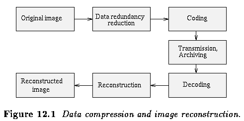
- Data compression methods can be divided into two principal groups:
- Information preserving compression permit error-free data reconstruction (lossless
compression).
- Compression methods with loss of information do not preserve the information
completely (lossy compression).
- In image processing, a faithful reconstruction is often not necessary in practice and
then the requirements are weaker, but the image data compression must not cause
significant changes in an image.
- Data compression success is usually measured in the reconstructed image by the mean
squared error (MSE), signal to noise ratio etc. although these global error measures do
not always reflect subjective image quality.
- Image data compression design - 2 parts.
- 1) Image data properties determination
- gray level histogram
- image entropy
- various correlation functions
- etc.
- 2) Appropriate compression technique design.
- Data compression methods with loss of information are typical in image processing.
Image data properties
- Entropy - measure of image information content
- If an image has G gray levels, and the probability of gray level k is P(k), then entropy
H_e, not considering correlation of gray levels, is defined as

- Information redundancy r is defined as

- where b is the smallest number of bits with which the image quantization levels can be
represented.
- A good estimate of entropy is usually not available.
- Image data entropy can however be estimated from a gray level histogram.
- Let h(k) be the frequency of gray level k in an image f, 0 <= k <= 2^b -1, and let
the image size be M x N.
- The probability of occurrence of gray level k can be estimated as

- and the entropy can be estimated as

- The information redundancy estimate is r = b- H_e. The definition of the compression
ratio K is then

- These formulae give theoretical limits of possible image compression.
- Example
- the entropy of satellite remote sensing data may be between 4 and 5, considering 8 bits
per pixel
- the information redundancy is between 3 and 4 bits
- these data can be represented by an average data volume of 4 to 5 bits per pixel with no
loss of information, and the compression ratio would be between 1.6 and 2.
Discrete image transforms in image data
compression
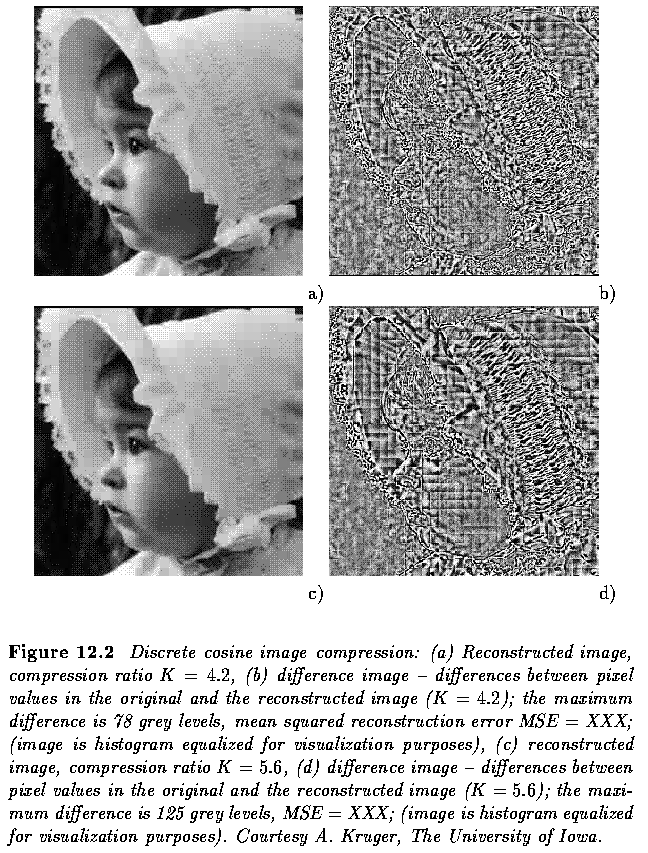
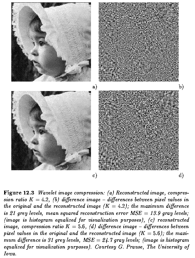
- Basic idea: image data representation by coefficients of discrete image transforms
- The transform coefficients are ordered according to their importance
- the least important (low contribution) coefficients are omitted.
- To remove correlated image data, the Karhunen-Loeve transform is the most
important.
- This transform builds a set of non-correlated variables with decreasing variance.
- The variance of a variable is a measure of its information content; therefore, a
compression strategy is based on considering only transform variables with high variance,
thus representing an image by only the first k coefficients of the transform.
- The Karhunen-Loeve transform is computationally expensive.
- Other discrete image transforms discussed in the previous chapter are computationally
less demanding.
- Cosine, Fourier, Hadamard, Walsh, or binary transforms are all suitable for image data
compression.
- If an image is compressed using discrete transforms, it is usually divided into
subimages of 8 x 8 or 16 x 16 pixels to speed up calculations, and then each subimage is
transformed and processed separately.
- The same is true for image reconstruction, with each subimage being reconstructed and
placed into the appropriate image position.
Predictive compression methods
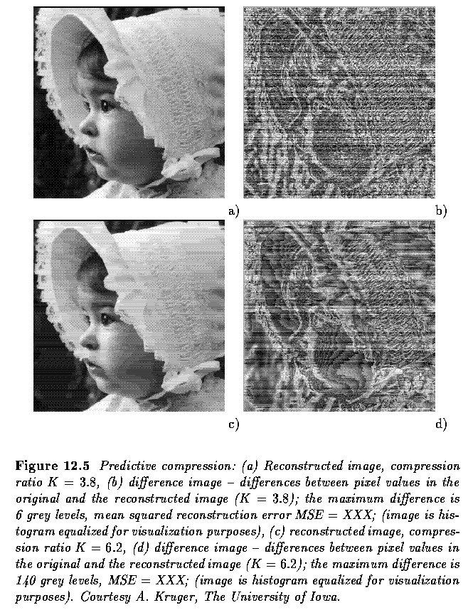
- Predictive compressions use image information redundancy (correlation of data) to
construct an estimate ~f(i,j) of the gray level value of an image element (i,j) from
values of gray levels in the neighborhood of (i,j).
- In image parts where data are not correlated, the estimate ~f will not match the
original value.
- The differences between estimates and reality, which may be expected to be relatively
small in absolute terms, are coded and transmitted together with prediction model
parameters -- the whole set now represents compressed image data.
- The gray value at the location (i,j) is reconstructed from a computed estimate ~f(i,j)
and the stored difference d(i,j)

- Differential Pulse Code Modulation (DPCM)

- Linear predictor of the third order is sufficient for estimation in a wide variety of
images.
- The estimate ~f can be computed as

- where a_1,a_2,a_3 are image prediction model parameters.
- These parameters are set to minimize the mean quadratic estimation error e,

- and the solution, assuming f is a stationary random process with a zero mean, using a
predictor of the third order, is

- where R(m,n) is the autocorrelation function of the random process f.
Vector quantization
Hierarchical and progressive compression
techniques
- A substantial reduction in bit volume can be obtained by merely representing a source as
a pyramid.
- Approaches exist for which the entire pyramid requires data volume equal to that of the
full resolution image..
- Even more significant reduction can be achieved for images with large areas of the same
gray level if a quadtree coding scheme is applied.

- Nevertheless, there may be an even more important aspect connected with this compression
approach - the feasibility of progressive image transmission and the idea of smart
compression.
- Progressive image transmission - transmitting all image data may not be necessary
under some circumstances - e.g., searching an image database looking for a particular
image.
- This approach is also commonly used to decrease the waiting time needed for the image to
start appearing after transmission and is used by World Wide Web image transmissions.
- In progressive transmission, the images are represented in a pyramid structure, the
higher pyramid levels (lower resolution) being transmitted first.
- The concept of smart compression is based on the sensing properties of human
visual sensors.
- The spatial resolution of the human eye decreases significantly with increasing distance
from the optical axis.
- Therefore, the human eye can only see in high resolution in a very small area close to
the point where the eye is focused.
- Similarly as with image displays, where it does not make sense to display or even
transmit an image in higher resolution than that of the display device, it is not
necessary to display an image in full resolution in image areas where the user's eyes are
not focused.
- The main difficulty remains in determining the areas of interest in the image on which
the user will focus.
- When considering a smart progressive image transmission, the image should be
transmitted in higher resolution in areas of interest first - this improves a subjective
rating of transmission speed as sensed by a human user.
- The areas of interest may be obtained in a feedback control manner from tracking the
user's eyes (assuming the communication channel is fast enough).
- This smart image transmission and compression may be extremely useful if applied to
dynamic image generators in driving or flight simulators, or to high definition
television.
Comparison of compression methods
- Transform-based methods better preserve subjective image quality, and are less sensitive
to statistical image property changes both inside a single image and between images.
- Prediction methods, on the other hand, can achieve larger compression ratios in a much
less expensive way, tend to be much faster than transform-based or vector quantization
compression schemes, and can easily be realized in hardware.
- If compressed images are transmitted, an important property is insensitivity to
transmission channel noise. Transform-based techniques are significantly less sensitive to
the channel noise - if a transform coefficient is corrupted during transmission, the
resulting image distortion is homogeneously spread through the image or image part and is
not too disturbing.
- Erroneous transmission of a difference value in prediction compressions causes not only
an error in a particular pixel, it influences values in the neighborhood because the
predictor involved has a considerable visual effect in a reconstructed image.
- Pyramid based techniques have a natural compression ability and show a potential for
further improvement of compression ratios. They are suitable for dynamic image compression
and for progressive and smart transmission approaches.
Other techniques
Coding
- Well known algorithms designed with serial data in mind are widely used in the
compression of ordinary computer files to reduce disk consumption.
- Very well known is Huffman encoding which can provide optimal compression and
error-free decompression.
- The main idea of Huffman coding is to represent data by codes of variable length, with
more frequent data being represented by shorter codes.
- Many modifications of the original algorithm exist, with recent adaptive Huffman coding
algorithms requiring only one pass over the data.
- More recently, the Lempel-Ziv (or Lempel-Ziv-Welch, LZW) algorithm of dictionary-based
coding has found wide favor as a standard compression algorithm.
- In this approach, data are represented by pointers referring to a dictionary of symbols.
- These, and a number of similar techniques, are in widespread use for de-facto standard
image representations which are popular for Internet and World Wide Web image exchange.
- GIF format (Graphics Interchange Format) is probably the most popular currently
in use.
- GIF is a creation of Compuserve Inc., and is designed for the encoding of RGB images
(and the appropriate palette with pixel depths between 1 and 8 bits.
- Blocks of data are encoded using the LZW algorithm.
- GIF has two versions - 87a and 89a, the latter supporting the storing of text and
graphics in the same file.
- TIFF (Tagged Image File Format) was first defined by the Aldus Corporation in
1986, and has gone through a number of versions to incorporate RGB color, compressed color
(LZW), other color formats and ultimately (in Version 6), JPEG compression (below) --
these versions all have backward compatibility.
JPEG and MPEG image compression
- There is an increasing effort to achieve standardization in image compression.
- The Joint Photographic Experts Group (JPEG) has developed an international
standard for general purpose, color, still-image compression.
- MPEG standard (Motion Picture Experts Group) was developed for full-motion video
image sequences with applications to digital video distribution and high definition
television (HDTV) in mind.
JPEG - still image compression
- JPEG is widely used in many application areas.
- Four compression modes are furnished
- Sequential DCT-based compression
- Progressive DCT-based compression
- Sequential lossless predictive compression
- Hierarchical lossy or lossless compression
- While the lossy compression modes were designed to achieve compression ratios around 15
with very good or excellent image quality, the quality deteriorates for higher compression
ratios.
- A compression ratio between 2 and 3 is typically achieved in the lossless mode.
- Sequential JPEG Compression consists of a forward DCT transform, a quantizer, and
entropy encoder while decompression starts with entropy decoding followed by dequantizing
and inverse DCT.
- In the compression stage, the unsigned image values from the interval [0,(2^b)-1] are
first shifted to cover the interval [-2^(b-1),2^(b-1)-1].
- The image is then divided into 8x8 blocks and each block is independently transformed
into the frequency domain using the DCT-II transform.
- Many of the 64 DCT coefficients have zero or near-zero values in typical 8x8 blocks
which forms the basis for compression.
- The 64 coefficients are quantized using a quantization table Q(u,v) of integers from 0
to 255 that is specified by the application to reduce the storage/transmission
requirements of coefficients that contribute little or nothing to the image content.
- The following formula is used for quantization

- After quantization, the dc-coefficient F(0,0) is followed by the 63 ac-coefficients that
are ordered in a 2D matrix in a zig-zag fashion according to their increasing frequency.
- The dc-coefficients are then encoded using predictive coding, the rationale being that
average gray levels of adjacent 8x8 blocks (dc-coefficients) tend to be similar.
- The last step of the sequential JPEG compression algorithm is entropy encoding.
- Two approaches are specified by the JPEG standard.
- The baseline system uses simple Huffman coding while the extended system uses arithmetic
coding and is suitable for a wider range of applications.
- Sequential JPEG decompression uses all the steps described above in the reverse order.
After entropy decoding (Huffman or arithmetic), the symbols are converted into DCT
coefficients and dequantized

- where again, the Q(u,v) are quantization coefficients from the quantization table that
is transmitted together with the image data.
- Finally, the inverse DCT transform is performed and the image gray values
are shifted back to the interval [0,(2^b)-1].
Practical Experiment 12.A
- Open xv (at the Unix prompt type 'xv').
- 1) Open the image
~dip/examples/images/theater.gif
- Save it in your directory as full-color images (under different names) in the
following formats:
- PBM
- TIFF - no compression
- TIFF - LZW compression
- JPEG 50%
- JPEG 25%
- JPEG 15%
- JPEG 5%
- Using ls -l command, compare the storage requirements of individual data formats.
- By re-opening the stored images, visually compare the image quality, do you see any
blocking artifacts if JPEG compression was employed?
- 2) Grab a portion of a text from this web page
- Store it in a grayscale mode using GIF and JPEG (75%, 25% and 5%).
- Compare the storage requirements.
- Compare quality.
- Order the image formats/compression parameters according to their storage
requirements.What do you conclude with respect to compression method choice, storage
requirements, image quality, and image content?
- In Progressive JPEG Compression, a sequence of scans is produced, each scan
containing a coded subset of DCT coefficients.
- A buffer is needed at the output of the quantizer to store all DCT coefficients of the
entire image.
- These coefficients are selectively encoded.
- Three algorithms are defined as part of the JPEG progressive compression standard;
- progressive spectral selection
- progressive successive approximation
- combined progressive algorithm.
- In the progressive spectral selection approach, the dc-coefficients are transmitted
first, followed by groups of low frequency and higher frequency coefficients.
- In the progressive successive approximation, all DCT coefficients are sent first with
lower precision and their precision increases as additional scans are transmitted.
- The combined progressive algorithm uses both of the above principles together.
- Sequential Lossless JPEG Compression
- The lossless mode of the JPEG compression uses a simple predictive compression algorithm
and Huffman coding to encode the prediction differences.
- Hierarchical JPEG Compression
- Using the hierarchical JPEG mode, decoded images can be displayed either progressively
or at different resolutions.
- A pyramid of images is created and each lower resolution image is used as a prediction
for the next higher resolution pyramid level.
- The three main JPEG modes can be used to encode the lower-resolution images - sequential
DCT, progressive DCT, or lossless.
- In addition to still image JPEG compression, motion JPEG (MJPEG) compression
exists that can be applied to real-time full-motion applications.
- However, MPEG compression represents a more common standard and is described below.
MPEG - full-motion video compression
- Video and associated audio data can be compressed using MPEG compression algorithms.
- Using inter-frame compression, compression ratios of 200 can be achieved in full-motion,
motion-intensive video applications maintaining reasonable quality.
- MPEG compression facilitates the following features of the compressed video
- random access,
- fast forward/reverse searches,
- reverse playback,
- audio-visual synchronization,
- robustness to error,
- editability,
- format flexibility, and
- cost tradeoff
- Currently, three standards are frequently cited:
- MPEG-1 for compression of low-resolution (320x240) full-motion video at rates of 1-1.5
Mb/s
- MPEG-2 for higher resolution standards like TV and HDTV at the rates of 2-80 Mb/s
- MPEG-4 for small-frame full-motion compression with slow refresh needs, rates of
9-40kb/s for video-telephony and interactive multimedia like video-conferencing.
- MPEG can be equally well used for both symmetric and asymmetric
applications.
- The video data consist of a sequence of image frames.
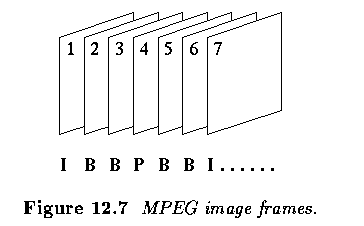
- In the MPEG compression scheme, three frame types are defined;
- intraframes I
- predicted frames P
- forward, backward, or bi-directionally predicted or interpolated frames B
- Each frame type is coded using a different algorithm and Figure below shows how the
frame types may be positioned in the sequence.
- I-frames are self-contained and coded using a DCT-based compression method similar to
JPEG.
- Thus, I-frames serve as random access frames in MPEG frame streams.
- Consequently, I-frames are compressed with the lowest compression ratios.
- P-frames are coded using forward predictive coding with reference to the previous I- or
P-frame and the compression ratio for P-frames is substantially higher than that for
I-frames.
- B-frames are coded using forward, backward, or bidirectional motion-compensated
prediction or interpolation using two reference frames, closest past and future I- or
P-frames, and offer the highest compression ratios.
- Note that in the hypothetical MPEG stream shown in Fig. 12.7, the frames must be
transmitted in the following sequence (subscripts denote frame numbers):
- I_1- P_4 - B_2 - B_3 - I_7 - B_5 - B_6 - etc.
- the frames B_2 and B_3 must be transmitted after frame P_4 to enable frame interpolation
used for B-frame decompression.
- Clearly, the highest compression ratios can be achieved by incorporation of a large
number of B-frames; if only I-frames are used, MJPEG compression results.
- The following sequence seems to be effective for a large number of applications.

- While coding the I-frames is straightforward, coding of P- and B-frames incorporates
motion estimation.
- For every 16x16 block of P- or B-frames, one motion vector is determined for P- and
forward or backward predicted B-frames, two motion vectors are calculated for interpolated
B-frames.
- The motion estimation technique is not specified in the MPEG standard, however block
matching techniques are widely used generally following the matching approaches.
- After the motion vectors are estimated, differences between the predicted and actual
blocks are determined and represent the error terms which are encoded using DCT.
- As usually, entropy encoding is employed as the final step.
- MPEG-1 decoders are widely used in video-players for multimedia applications and on the
World Wide Web.
Last Modified: October 25, 2000
![[Go Back]](../IMAGES/next.gif)


![]()


![]()

![]()
![]()


![]()

![]()