55:148 Digital Image Processing
55:247 Image Analysis and Understanding
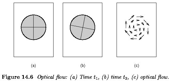
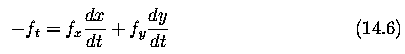
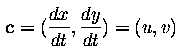
Chapter 14, Motion Analysis:
Optical flow
Chapter 14.2 Overview:
- Optical flow reflects the image changes due to motion during a time interval
dt
- Optical flow field is the velocity field that represents the three-dimensional
motion of object points across a two-dimensional image
- optical flow should not be sensitive to illumination changes and motion
of unimportant objects (e.g., shadows)
- non-zero optical flow is detected if a fixed sphere is illuminated by
a moving source
- mooth sphere rotating under constant illumination provides no optical
flow
Optical flow computation
- Assumptions:
- The observed brightness of any object point is constant over time.
- Nearby points in the image plane move in a similar manner (velocity
smoothness constraint).
- Suppose we have a continuous image; f(x,y,t)
- Representing a dynamic image as a function of position and time permits
it to be expressed as a Taylor series:

- f_x, f_y, f_z denote the partial derivatives of f
- immediate neighborhood of (x,y) is translated some small distance (dx,dy)
during the interval dt; that is, we can find dx,dy,dt such that

If $dx,dy,dt$ are very small, the higher-order terms in equation vanish and
the goal is to determine velocity
f_x, f_y, f_t can be computed, or at least approximated, from f(x,y,t)
Motion velocity can then be estimated as
-
where grad(f) is a two-dimensional image gradient
- from equation (14.7) ... the gray-level difference f_t at the same location
of the image at times t and t+dt is a product of spatial gray-level difference
and velocity in this location according to the observer
- Equation (14.7) does not specify the velocity vector completely - provides
the component in the direction of the brightest gradient
- So - a smoothness constraint is introduced; that is, the velocity vector
field changes slowly in a given neighborhood.
- The approach reduces to minimizing the squared error quantity


-
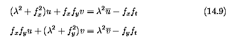
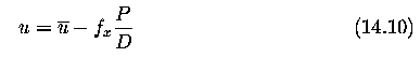
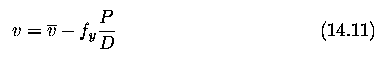
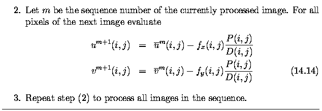
Determination of the optical flow is then based on a Gauss-Seidel
iteration method using pairs of (consecutive) dynamic images
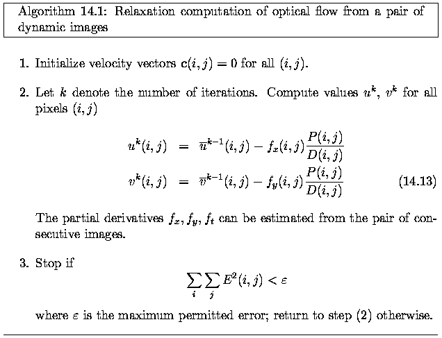
-
If more than two images are to be processed, computational
efficiency may be increased by using the results of one iteration to initialize
the current image pair in sequence:
-
Both these algorithms are naturally parallel
-
The iterations may be very slow - thousands of iterations
are needed until convergence if a second-order smoothness criterion is applied
-
However, the first 10-20 iterations usually leave an error
smaller than the required accuracy, and the rest of the iterative process
is then very gradual.
-
If the differences dx,dy,dt are very small, all the higher-order
terms vanish in the continuous derivative of equation (14.4).
-
This is often not the case if subsequent images are not
taken frequently enough.
-
As a result, the higher-order terms do not vanish and an
estimation error results if they are neglected.
-
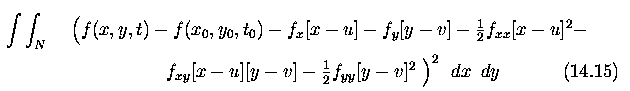
To decrease this error, the second-order terms may be considered
in the Taylor series, and the problem becomes a minimization of an integral
over a local neighborhood N
-
This minimization is rather complex and may be simplified for image
points that correspond to corners
-
Let the co-ordinate system be aligned with the main curvature direction
at (x_0,y_0); then f_{xy}=0 and the only non-zero second-order derivatives
are f_{xx} and f_{yy}
-
However, at least one of them must cross zero at (x_0,y_0) to get a
maximum gradient:
-
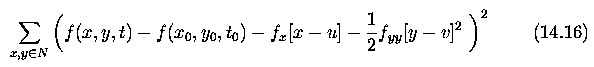
If, say, f_{xx}=0, then f_x goes to max and f_y=0
-
With these assumptions, equation (14.15) simplifies,
and the following formula is minimized
-
A conventional minimization approach of differentiating
equation (14.16) with respect to u and v and equating to zero results
in two equations in the two velocity components u,v
Global and local optical flow estimation
- Violations of constant brightness and velocity smoothness assumptions ...
errors
- Violation is quite common.
- optical flow changes dramatically in highly textured regions, around
moving boundaries, depth discontinuities, etc.
- ... global relaxation methods of optical flow computation ... find the
smoothest velocity field consistent with the image data;
- ability to propagate local constraints globally
- However - not only constraint information but also all optical flow estimation
errors propagate across the solution
- ... a small number of problem areas may cause widespread errors and poor
optical flow estimates
- ... local optical flow estimation appears a natural solution to the difficulties
- the image is divided into small regions where the assumptions hold
- solves the error propagation problem but
- in regions where the spatial gradients change slowly, the optical flow
estimation becomes ill-conditioned because of lack of motion information,
and it cannot be detected correctly
- If a global method is applied to the same region, the information from
neighboring image parts propagates and represents a basis for optical
flow computation even if the local information was not sufficient by itself.
- The conclusion of this comparison is that global sharing of information
is beneficial in constraint sharing and detrimental with respect to error
propagation
- Coping with the smoothness violation problem - to detect regions in which
the smoothness constraints hold.
- main problem - selecting a threshold to decide which flow value difference
should be considered substantial
- threshold too low, many points are considered positioned along flow
discontinuities,
- threshold too high, some points violating smoothness remain part of
the computational net
Optical flow in motion analysis
- Optical flow gives a description of motion and can be a valuable contribution
to image interpretation even if no quantitative parameters are obtained from
motion analysis.
- Optical flow can be used to study a large variety of motions
- moving observer and static objects
- static observer and moving objects
- both moving
- Optical flow analysis does not result in motion trajectories
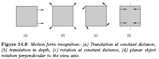
- Motion is usually combination of four basic elements
- Translation at constant distance from the observer
- Translation in depth relative to the observer
- Rotation at constant distance about the view axis
- Rotation of a planar object perpendicular to the view axis
- Optical-flow based motion analysis
- based on
- Translation at constant distance is represented as a set of parallel
motion vectors
- Translation in depth forms a set of vectors having a common focus of
expansion
- Rotation at constant distance results in a set of concentric motion
vectors
- Rotation perpendicular to the view axis forms one or more sets of vectors
starting from straight line segments
- Exact determination of rotation axes and translation trajectories can be
computed, but with a significant increase in difficulty of analysis.
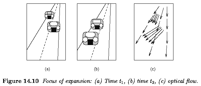
- translational motion
- if translation is not at constant depth, then optical flow vectors are
not parallel, and their directions have a single focus of expansion (FOE)
- if the translation is at constant depth, the FOE is at infinity
- if several independently moving objects are present in the image, each
motion has its own FOE (Figure below, where an observer moves in a car
towards other approaching cars on the road)
-
Mutual velocity
- mutual velocities in directions x,y,z ... c_x=u, c_y=v, c_z=w
- z gives information about the depth (note that z>0 for points in front of
the image plane).
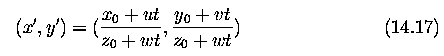
- image co-ordinates x', y'.
- from perspective considerations, if (x_0,y_0,z_0) is the position of some
point at time t_0=0,
- then the position of the same point at time t can, assuming unit focal distance
of the optical system and constant velocity, be determined as
-
FOE determination
- assume motion directed towards an observer; as t goes to minus infinity,
the motion can be traced back to the originating point at infinite distance
from the observer
- motion towards an observer continues along straight lines and the originating
point in the image plane is
-
the same equation holds for t going to plus infinity and motion away
from observer
Distance (depth) determination
- presence of a z co-ordinate in equation (14.17) ... current distance of
a moving object from the observer's position
- assuming points of the same rigid object and translational motion, at least
one actual distance value must be known to evaluate the distance exactly
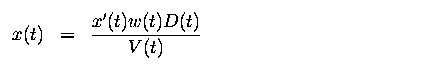
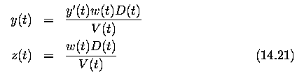
- let D(t) be the distance of a point from the FOE, measured in a two-dimensional
image
- let V(t) be its velocity dD/dt. The relationship between these quantities
and the optical flow parameters is then
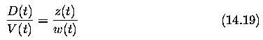
- ... basis for determination of distances between moving objects
- assuming an object moving towards the observer, the ratio z/w specifies
the time at which an object moving at a constant velocity w crosses the image
plane
- ... knowledge of the distance of any single point in an image which is moving
with a velocity w along the z axis, it is possible to compute the distances
of any other point in the image that is moving with the same velocity w
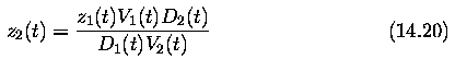
where z1(t) is the known distance
z2(t) is the unknown distance
The above equations cover both moving object and moving camera
Collision Prediction
-
motion of a robot in the real world, where the optical
flow approach is able to detect potential collisions with scene objects
-
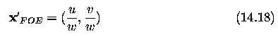
observer motion seen from optical flow representation aims
into the FOE of this motion
-
co-ordinates of this FOE are (u/w,v/w)
-
origin of image co-ordinates (the imaging system focal
point) proceeds in the direction s=(u/w,v/w,1) and follows a path in real-world
co-ordinates at each time instant defined as a straight line,
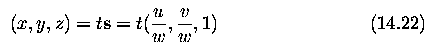
t represents time
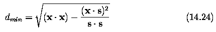
Position of an observer x_obs when at closest point to some x in real world
is
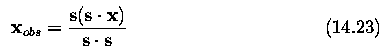
the smallest distance d_min between point x and observer during observer
motion is
Last Modified: May 19, 1997
![[Go Back]](../IMAGES/next.gif)